Flameproof transformer stations IT3Sm
Description
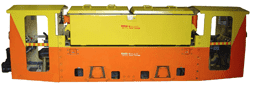
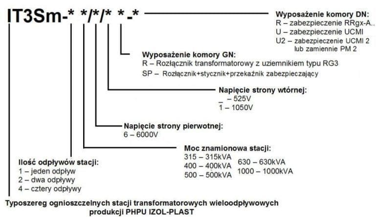
Flameproof multi-outflow transformer stations type IT3Sm- * * / * / * * – * are designed to supply electrical equipment in the underground of mines in workings classified as grade “a”, “b” or “c” of methane explosion hazard and class “A” or “B” of the coal dust explosion hazard.
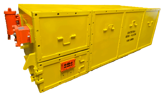
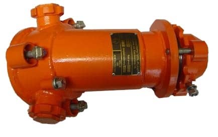
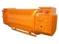
Flameproof multi-outlet transformer stations IT3Sm- * * / * / * * – * constitute a complete substation consisting of a power transformer, switchgear and protection devices. The whole thing is placed in a flameproof enclosure adapted for easy and quick transport and installation.
The applied electric power protections and the adopted control and cooperation system with technological interlocks with the use of intrinsically safe circuits allow for safe cooperation with devices supplying mining machines.
Construction
| Type | Data |
|---|---|
| Ambient temperature: | -10oC to +40oC |
| Relative humidity at +40oC: | from 95 % |
| Maximum relative humidity at a temperature of +25oC or at lower temperatures with condensation: | 100% |
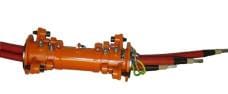
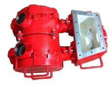
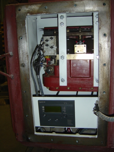
Flame-proof transformer stations of the series of types consist of three basic chambers: HV chamber, power transformer chamber and LV chamber.
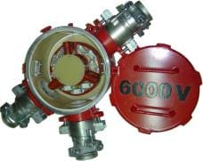
- Version I – GN chamber made in the form of a cylinder with closed flameproof door through a locking ring, equipped with transformer switch disconnector with earthing switch type RG3 for disconnecting the station from voltage when the transformer is idle. The equipment includes IT3Sm- * * / * / * R- * stations.
- Version II – GN chamber with a structure closed on both sides with two hinged rectangular doors locked with hexagonal screws, equipped with a transformer switch disconnector with an earthing switch type RG3, a Rollarc type 400 contactor and a protection relay, type SEPAM. The equipment includes IT3Sm- * * / * / * SP- * stations.
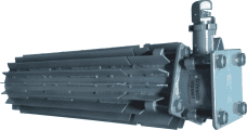
- Version I – power transformer chamber built as a flameproof casing in the form of a ladle with air cooling made of two rows of adjacent pipes along the side walls. Chamber for 315kVA and 400kVA transformers.
- Version II – the chamber is made similarly to version I. Chamber for transformers with the capacity of 500kVA and 630kVA.
- Version III – power transformer chamber built as a flameproof casing in the form of a ladle with air cooling made of flat bars adjacent to the walls of the ladle. Chamber for 1000kVA transformers.
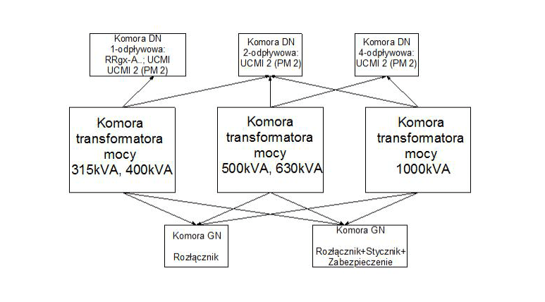
- Version I – DN chamber made in the form of a cylinder with closed flameproof doors through a locking ring, this applies to stations type IT3Sm-1 * / * / * * -R, IT3Sm-1 * / * / * * -U, IT3Sm-1 * / * / * * -U2.
- Version II – DN chamber with a structure closed on both sides with two hinged rectangular doors locked with hexagonal screws, this applies to transformer stations type IT3Sm-2 * / * / * * – *. The 2-outlet DN chamber is designed for transformer stations with the capacity of 400kVA, 500kVA, 630kVA and 1000kVA.
- Version III – DN chamber with a structure closed on both sides through four hinged rectangular doors locked with hexagonal screws, this applies to the station type IT3Sm-4 * / * / * * – *. The 4-outlet DN chamber is intended only for 500kVA, 630kVA and 1000kVA transformer stations.
- leaving transformer stations in cages in their entirety and in a normal position,
- the station must be properly wedged in order to avoid shifting in the cage during transport,
- in the case of too small dimensions of the cage, the transformer station can be transported properly attached underneath it. In this case, the rate of lowering the cage should not exceed 0.5 m / sec, and the cross-section of the ropes should guarantee safe lifting of the station.
- the driving speed of the station should not exceed 6 m / sec.,
- it is forbidden to transport the station together with other carriages on the train.
The stations should be stored in dry, well-ventilated rooms with a practically constant temperature. The ambient temperature range should be -10oC to + 40oC due to the electrical apparatus and the RRgx-A .., UCMI, UCMI 2 or PM-2 safety device. During storage, particular attention should be paid to protecting electrical apparatus and devices against moisture. After transport from the manufacturer, after storage and before transport to the place of installation in each station, before putting into service, the mechanisms and electrical apparatus should be checked.
When selecting the place of installation, it is necessary to take into account the further relocation of the station as the mining work progresses, and consider the possibility of carrying out the transport works in safe conditions later.
Set up the station as close as possible to the receivers. The maximum distance of the receivers should be such that the voltage drops on the cables are within the specified limits.
The location of the station should provide convenient access to all instruments and provide convenient conditions for maintenance, service and operation.
Flameproof multi-outlet transformer stations type IT3Sm- * * / * / * * – * can work as suspended on appropriate certified slings intended for this purpose.
Technical data of flameproof transformer stations type IT3Sm- * * / * / * * – *
Flame-proof transformer station type IT3Sm- * * / * / * * – * has the following ratings:
| power Sn: | 315 kVA, 400 kVA, 500 kVA, 630 kVA, 1000 kVA |
| primary rated voltage U1n: | 6000 V ±5% |
| secondary rated voltage U2n: | 525 V or 1050 V |
| gear adjustment on the GN side: | -5%, 0%, +5% |
| frequency: | 50 Hz |
| connection arrangement: | Yy0 |
| cooling: | AN-AN |
| ambient temperature | from -10oC to +40oC |
Flame-proof transformer stations type IT3Sm- * * / * / * * – * have the following rated and short-circuit data:
| Station type | Power Sn | Rated voltage | Regulation gears | Frequency | number phases | Rated current | System of connections | ||
|---|---|---|---|---|---|---|---|---|---|
| side GN U1n | side DN U2n | side GN I1n | side DN I2n | ||||||
| kVA | V | V | % | Hz | – | A | A | – | |
| IT3Sm-* 315/6 *-* | 315 | 6000±5% | 525 | -5 | 50 | 3 | 30,3 | 346 | Yy0 |
| IT3Sm-* 400/6 *-* | 400 | 6000±5% | 525 | ±5 | 50 | 3 | 38,5 | 440 | Yy0 |
| IT3Sm-* 400/6/1 *-* | 400 | 6000±5% | 1050 | ±5 | 50 | 3 | 38,5 | 220 | Yy0 |
| IT3Sm-* 500/6 *-* | 500 | 6000±5% | 525 | ±5 | 50 | 3 | 48,2 | 550 | Yy0 |
| IT3Sm-* 630/6/1 *-* | 630 | 6000±5% | 1050 | ±5 | 50 | 3 | 60,6 | 346 | Yy0 |
| IT3Sm-* 1000/6/1 *-* | 1000 | 6000±5% | 1050 | ±5 | 50 | 3 | 96 | 550 | Yy0 |
| Station type | Power Sn | Short circuit voltage | Losses | Total weight | Work | Cooling | Insulation class | Level of security | |
| Idle P0 | Loaded P | ||||||||
| kVA | % | W | W | kg | – | – | – | – | |
| IT3Sm-* 315/6 *-* | 315 | 3,7 | 1400 | 2900 | 3100 | C | AN-AN | C (H) | IP-54 |
| IT3Sm-* 400/6 *-* | 400 | 4,3 | 2300 | 3700 | 3300 | C | AN-AN | C (H) | IP-54 |
| IT3Sm-* 400/6/1 *-* | 400 | 4,3 | 2300 | 3500 | 3300 | C | AN-AN | C (H) | IP-54 |
| IT3Sm-* 500/6 *-* | 500 | 4,1 | 2300 | 3500 | 4300 | C | AN-AN | C (H) | IP-54 |
| IT3Sm-* 630/6/1 *-* | 630 | 4,3 | 2500 | 5200 | 4700 | C | AN-AN | C (H) | IP-54 |
| IT3Sm-* 1000/6/1 *-* | 1000 | 4,0 | 2700 | 5300 | 5600 | C | AN-AN | C (H) | IP-54 |
Series of types of flameproof multi-outlet transformer stations type IT3Sm-2 * / * / * * – *
(single-drain stations):
| Type | Power Sn | Side voltage DN U2n | Drain current I2n | |
| Switch disconnector type RG3 | Switch disconnector type RG3 + contactor Rollarc type 400D + Relay protection type SEPAM | |||
| IT3Sm-1 315/6 R-R, IT3Sm-1 315/6 R-U, IT3Sm-1 315/6 R-U2 | ——————————- | 315 kVA | 525 V | 346 A |
| IT3Sm-1 400/6 R-R, IT3Sm-1 400/6 R-U, IT3Sm-1 400/6 R-U2 | IT3Sm-1 400/6 SP-R, IT3Sm-1 400/6 SP-U, IT3Sm-1 400/6 SP-U2 | 400 kVA | 525 V | 440 A |
| IT3Sm-1 400/6/1 R-R, IT3Sm-1 400/6/1 R-U, IT3Sm-1 400/6/1 R-U2 | IT3Sm-1 400/6/1 SP-R, IT3Sm-1 400/6/1 SP-U, IT3Sm-1 400/6/1 SP-U2 | 400 kVA | 1050 V | 220 A |
Series of types of flameproof multi-outlet transformer stations type IT3Sm-2 * / * / * * – *
(two-outlet stations):
| Type | Power Sn | Site tension DN U2n | Drain current I2n | |
| Switch disconnector type RG3 | Switch disconnector type RG3 + contactor Rollarc type 400D + Relay protection type SEPAM | |||
| IT3Sm-2 400/6 R-U2 | IT3Sm-2 400/6 SP-U2 | 400 kVA | 525 V | 220 A |
| IT3Sm-2 400/6/1 R-U2 | IT3Sm-2 400/6/1 SP-U2 | 400 kVA | 1050 V | 110 A |
| IT3Sm-2 500/6 R-U2 | IT3Sm-2 500/6 SP-U2 | 500 kVA | 525 V | 275 A |
| IT3Sm-2 630/6/1 R-U2 | IT3Sm-2 630/6/1 SP-U2 | 630 kVA | 1050 V | 173 A |
| IT3Sm-2 1000/6/1 R-U2 | IT3Sm-2 1000/6/1 SP-U2 | 1000 kVA | 1050 V | 275 A |
Series of types of flameproof multi-outlet transformer stations type IT3Sm-4 * / * / * * – *
(four-outlet stations):
| Type | Power Sn | Site tension DN U2n | Drain current I2n | |
| Switch disconnector type RG3 | Switch disconnector type RG3 + contactor Rollarc type 400D + Relay security type SEPAM | |||
| IT3Sm-4 500/6 R-U2 | IT3Sm-4 500/6 SP-U2 | 500 kVA | 525 V | 137 A |
| IT3Sm-4 630/6/1 R-U2 | IT3Sm-4 630/6/1 SP-U2 | 630 kVA | 1050 VV | 86 A |
| IT3Sm-4 1000/6/1 R-U2 | IT3Sm-4 1000/6/1 SP-U2 | 1000 kVA | 1050 V | 137 A |
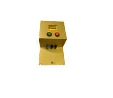
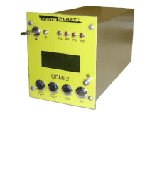
The UCMI 2 control and protection device can be used interchangeably with the PM-2 microprocessor relay. These protections are used in the DN equipment compartment of the IT3Sm-1 * / * / * * -U2, IT3Sm-2 * / * / * * – * and IT3Sm-4 * / * / * * – * stations. The equipment of the DN chamber is adapted to the connection of both UCMI 2 or PM-2 type protections.
The universal control and protection device UCMI and UCMI 2 can be used in power supply stations for frequency converters. The UCMI and UCMI 2 devices control IT networks in the frequency range 0.2 – 60 Hz.
Schemes
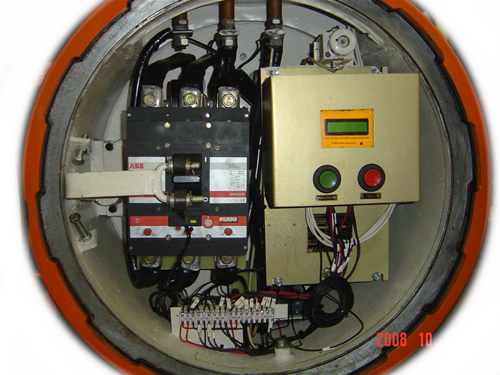
| Assembly diagram of IT3Sm- * * / * / * SP- * transformer station with switch disconnector, contactor and protection relay: | 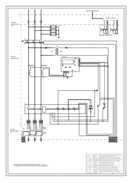 |
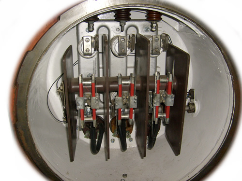
| Assembly diagram of the IT3Sm-1 * / * / * R-U transformer station with UCMI protection with a circuit breaker and a shunt release: | 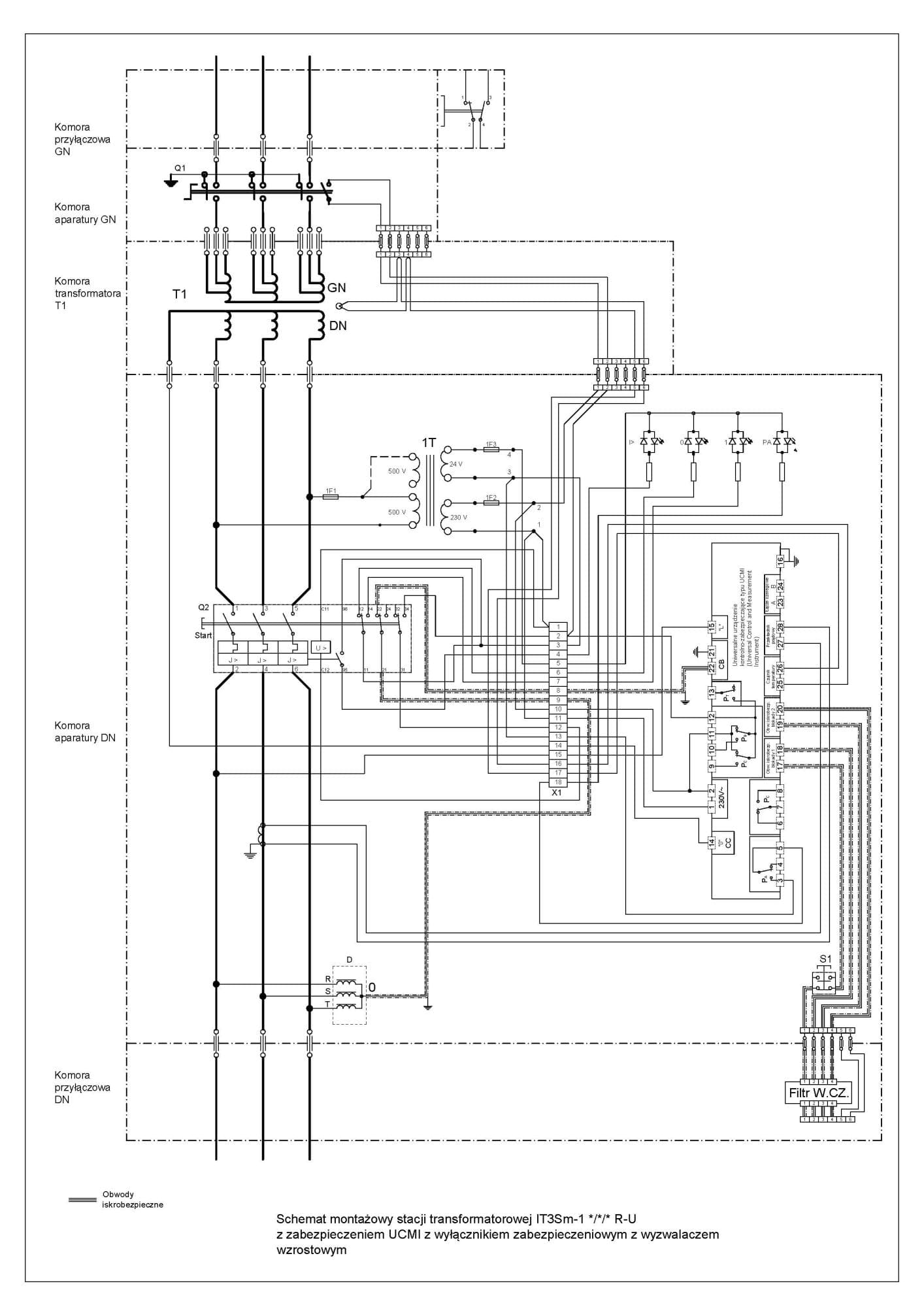 |
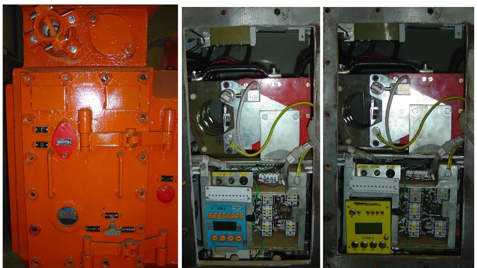
| Assembly diagram of the IT3Sm-2 * / * / * R-U2 transformer station with UCMI 2 protection or PM 2 type protection with a vacuum contactor: | 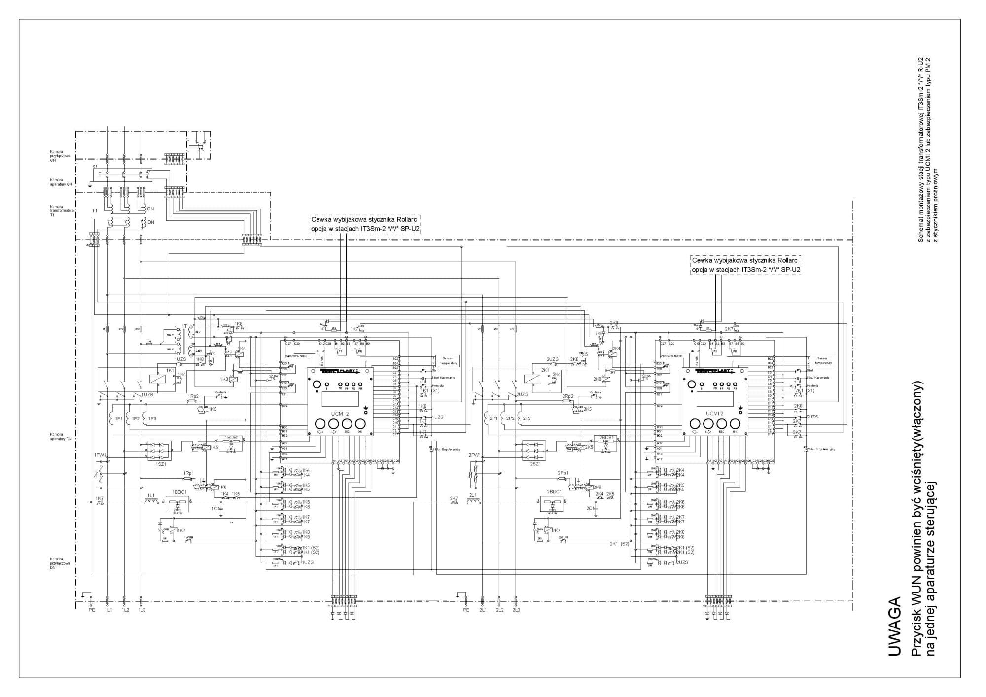 |
Certificate
Flameproof multi-outlet transformer stations type IT3Sm-1 * / * / * * – *, IT3Sm-2 * / * / * * – *, IT3Sm-4 * / * / * * – * have EC type examination certificate: OBAC 15ATEX0006X of 27 August 2015 issued by the Center for Testing, Attestation and Certification OBAC Sp. z o. o. in Gliwice.
Center for Testing, Attestation and Certification OBAC Sp. z oo, Notified Body No. 1461 in accordance with Article 9 of Council Directive 94/9 / EC of 23 March 1994, certifies that the above-mentioned device or protective system has been checked for compliance with the basic safety and health requirements regarding the design, construction of the device and system for use in potentially explosive atmospheres specified in Annex II to this Directive.
The basic requirements of safety and health protection were implemented by meeting the requirements of the following standards:
PN-EN 60079-0:2013 (EN 60079-0:2012),
PN-EN 60079-1:2010 (EN 60079-0:2007).
Flameproof multi-outlet transformer stations IT3Sm-1 * / * / * * – *, IT3Sm-2 * / * / * * – *, IT3Sm-4 * / * / * * – * are marked with:
| OBAC 15ATEX0006X I M2 Ex d [ib] I Mb |
Download the catalog card:
![]() Flameproof transformer stations of the series IT3Sm- * * / * / * * – *
Flameproof transformer stations of the series IT3Sm- * * / * / * * – *