Universal Control and Safety Device UCMI 2
Description
Application:
Universal control and protection device type UCMI 2 (Universal Control and Measurement Instrument) protects against the effects of insulation deterioration in AC power networks with a rated voltage up to 1050 V, 50 Hz, including mine networks supplying mining equipment in explosion-proof casings.
UCMI 2 device can be used in:
- transformer units,
- compact stations supplying longwall equipment in underground mining plants,
- flameproof transformer stations,
- flameproof contactor switches,
The UCMI 2 device performs the following control and protection functions:
- central-blocking leakage protection,
- over-current protection (overload, short-circuit and asymmetric element)
- temperature protection
- protection of earthing continuity control
- local non-intrinsically safe and intrinsically safe remote control
- control of warning signaling
- visualization on the LCD display of the measurement results and the operating status of the device
- sending information about the operating status of the device to designated analysis points
The UCMI 2 device measures the insulation condition of the tested network, disconnecting it from voltage in the event of a decrease in the insulation condition and preventing voltage supply to a power network with a reduced insulation level. It also protects the network against the effects of overloads, short circuits, current asymmetry and exceeding the permissible temperature. The UCMI 2 device displays the insulation status, phase currents, temperature and voltage of the tested network on the LCD display.
The cooperation of the blocking element with the network is carried out by a certified set of artificial zero reactors from Izol-Plast.
Counteracting threats:
The universal control and protection device type UCMI 2 has been designed and is manufactured to counteract hazards in accordance with the Regulation of the Minister of Economy of December 22, 2005 on essential requirements for equipment and protective systems intended for use in potentially explosive atmospheres.(Dz.U. z 2005r. nr 263, poz. 2203).
Conditions for using UCMI 2:
The use of UCMI 2 device in potentially explosive atmospheres will be specified each time for devices in which it will be installed and meeting the following standards:
- PN-G-42040:1996 -Protective and safety measures in mine power engineering – Leakage protection – Requirements and tests,
- PN-EN 60079-1:2012 – Explosive atmospheres – Part 1: Protection of equipment with flameproof enclosures “d”,
- PN-EN 60079-11:2012 -Explosive atmospheres – Part 11: Equipment protection with intrinsic safety “i”.
Technical data
| Type | Data |
|---|---|
| Supply voltage: | 24 V ±20%, 50 Hz |
| Type of work: | continuous |
| Power consumption: | ≤ 24 VA |
| The degree of protection of the housing: | IP 40 |
| External dimensions: | 122 x 106 x 205 mm |
| Contact load: | 2.5 A / 230 V |
| Mass: | 3 kg |
Rated data
UCMI operating conditions 2:
| Type | Data |
|---|---|
| Rated voltage of the controlled network | Un ≤ 1050 V |
| Voltage fluctuations | 0.8⋅Un < Un ≤ 1,2⋅Un |
| The content of higher harmonics | ≤ 5% |
| Mains frequency fluctuation | ± 4% |
| Presence of DC voltages in the network | lack |
| Allowable capacity of the controlled network | 1 µF per phase |
| Height above sea level | -2000 m ÷ 2000 m |
| Ambient temperature | -10 oC ÷ 70 oC |
| Relative humidity at temperatures up to 40oC | 95% |
| Max. relative humidity up to 25oC or at lower temperatures with condensation | 100% |
| Air surrounding the protection | Free from water, dust and chemically active gases |
| Mechanical vibrations at the mounting point | Sinusoidal vibrations with an amplitude of 0.5 g in the frequency range 5 ÷ 35 Hz |
| Air surrounding the protection | Free from water, dust and chemically active gases |
| The location of the device | any |
Network insulation resistance measuring circuit parameters:
| Type | Data |
|---|---|
| Output voltage of the measuring circuit | Un = 25 V DC |
| Output current of the measuring circuit | In = 0,25 mA |
| Output capacity of the measuring circuit | Co max = 5 µF |
| Output inductance of the measuring circuit | Lo max = 600 H |
| A feature of the intrinsic safety of the circuit | non-ignition circuit |
| Resistance measuring range | 0 ÷ 100 kΩ |
| Resistance setting range for the activation threshold | 1 ÷ 99 kΩ |
| Resistance setting range for the return threshold | 1 ÷ 99 kΩ |
| Low insulation alarm threshold | 1 ÷ 99 kΩ |
| Insulation resistance measurement compensation | 0 ÷ 99 kΩ |
| Setting range of the time delay of the resistance measuring element | 5 ÷ 1000 ms |
Output parameters of intrinsically safe circuits:
| Type | Data |
|---|---|
| Output voltage of the measuring circuit | Uo = ±11,7 V |
| Output current of the measuring circuit | Io = ±16,6 mA |
| Output power of the measuring circuit | Po = 48 mW |
| Input inductance of the power circuit | Li = 0 H |
| Input capacity of the measuring circuit | Ci = 0 F |
| Output inductance of the measuring circuit | Lo = 0,65 H |
| Output capacity of the measuring circuit | Co = 5 µF |
Parameters of the current measuring circuit:
| Type | Data |
|---|---|
| Input measuring voltage | 0 ÷ 8 Vrms |
| Rated current setting range In | 30 ÷ 800 A |
| Transformer ratio setting range N | 0,1 ÷ 25,5 mV/A |
| Setting range of the short-circuit module W | 2,5 ÷ 10 |
| The activation threshold of an asymmetric element | 0,5 In |
| Setting range of an asymmetric element L | 30 ÷ 100% |
| Setting range of the time delay of the short-circuit module | 5 ÷ 70 ms |
| Time delay setting range of an asymmetric element | 5 ÷ 200 ms |
| Current limitation | 30 ÷ 2000 A |
| Setting range for the time delay of the current limitation element | 5 ÷ 200 ms |
| Setting range for the time delay of the overload element | 0 ÷ 120 min |

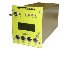
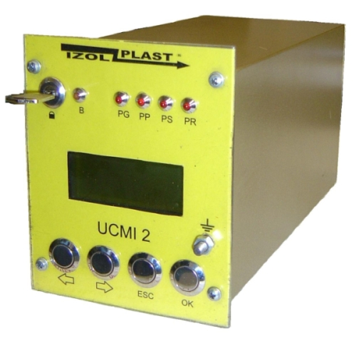
The dimensions of UCMI 2 are shown in the adjacent drawing.
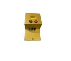
The steel housing, consisting of a cuboid consisting of a top, bottom and side walls, as well as a removable front and back cover, is protected with anti-corrosive coatings.
On the front cover there is a sight glass for observing the liquid crystal display and buttons: “⇐”, “⇒”, “ESC”, “OK” for changing the parameters of the device as well as LEDs indicating the operating status of the device. On the back of the housing there are three sockets for connecting the device.
The UCMI device should be securely attached to the supporting structure in a housing (ordinary) of at least IP 54 protection or a flameproof housing (e.g. in the low voltage apparatus chamber of mine, mobile transformer stations of explosion-proof or shielded construction), using 2 bolts. Electrical connection should be made by trained personnel, in accordance with technical drawings and technical documentation. The figure below shows the connection diagram of the UCMI 2 device with a vacuum contactor.

Diagram of the IT3Sm-1 * / * / * R-U2 single-outlet station
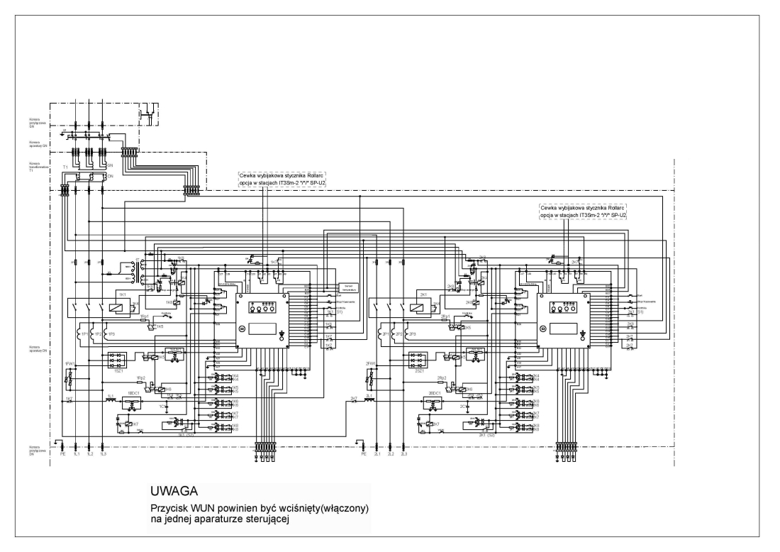
Diagram of the IT3Sm-2 * / * / * R-U2 two-outflow station
Certificates
On 09/08/2014 universal control and protection device type UCMI 2 received the EC-type examination certificate: FTZU & nbsp; 11 ATEX 0145X Physical-Technical Testing Institute (Fyzikálne technickz zkusebni ustav, sp), Notified Body No. 1026 in accordance with Article 9 of the Council Directive 94/9 / EC of 23 March 1994, certifies that the above-mentioned device or protective system has been checked for compliance with the basic safety and health protection requirements regarding the design, construction of the device and protective system intended for use in conditions potentially explosive atmospheres listed in Annex II to this Directive.
Based on the Technical Opinion No. OBAC / 591 / TE / 12 of 18.01.2013 of the OBAC Attestation and Certification Center, it is stated that the UCMI 2 universal control and protection device complies with the general design solutions technical requirements. Detailed information can be found in the above-mentioned technical opinion.
The universal control and protection device UCMI 2 can be used in power supply stations for frequency converters.
The basic requirements of safety and health protection were implemented by meeting the requirements of the following standards:
- PN-EN 60079-0:2012
- PN-EN 60079-11:2012
The universal control and protection device of the UCMI 2 type is marked:
 FTZU 11 ATEX 0145X
I (M1) [Ex ia Ma] I
![]() 1461
1461
Download the catalog card: